|
|
|
|
|
|
by spchampion2
1522 days ago
|
|
|
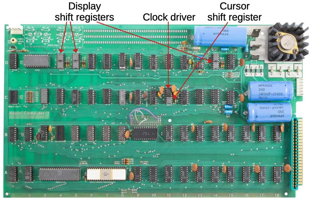
I would love a bit of explanation about why the shift register ICs were spread out so far on the circuit board. Your diagram [1] shows two sets right next to each other with a third set on practically the opposite side of the board. It would almost seem easier to have them all right next to each other so they could cleanly shift. Why the separation? 1 - https://static.righto.com/images/apple-shift-reg/board-label... |
|
|
But why are they at opposite sides of the board? I think that is because the shift registers are very simple chips as far as connections, just 6 pins in use. So it is a lot easier to put them at the edges than a chip that has 16 pins in use, since there are only a few lines to route.
Note that the large vertical gap between rows of ICs so there is room for all the horizontal wiring. So I think the board had more capacity for horizontal wiring than vertical wiring. As a result, related circuitry is in the same row. E.g. the display stuff is in the same row (mostly), the CPU, peripheral adapter, and RAM are in the same row, and so forth. I think the video circuitry is in the top row so they can put the output connector at the back.
I'm sure there are more constraints on routing this board that I can only guess at. Even from a quick look, there seem to be a lot of factors.