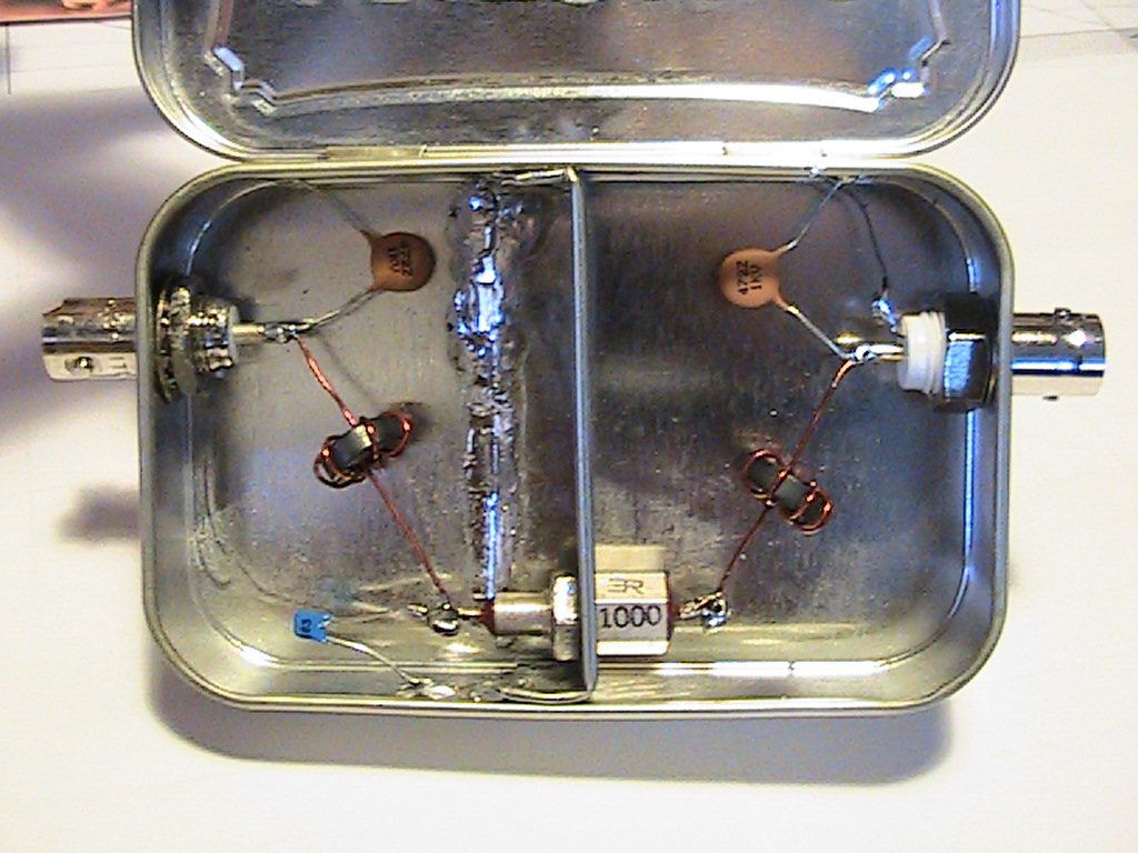
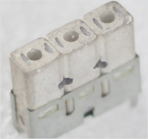
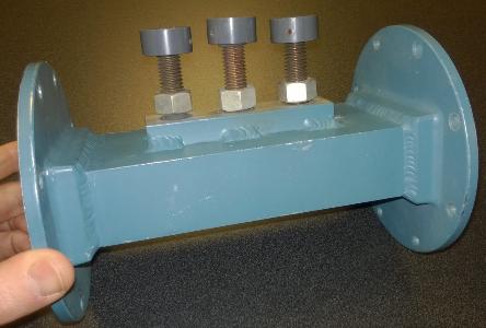
| I'd like to add a few practical examples - a LC filter might look like this https://www.qsl.net/kp4md/lpfilter2.jpg, by poking the turns of the coil, you change the frequency and width; with a real-time display on a VNA you can fine-tune a filter with a bit of practice (I't maybe better to have linear, not toroid, coils for this) - a ceramic filter might look like this http://www.pro-line.co.kr/base/img/_proline/product/Ceramic_.... We were recently optimizing filters in our radar and I said something like "this filter is cool but it's about 30 MHz (0.5%) too low" and our RF wizard said "no problem we will sand off a tiny bit on one end" [changing the shape and thus the resonant frequency]. Again you observe the characteristics of the filter and poke it and tune it to your needs. The above is called S21 parameter of the filter. Basically "what goes through and what not" (depending on frequency). https://en.wikipedia.org/wiki/Scattering_parameters - when you are chaining amplifiers, there is a problem with reflected power - the next stage input will not eat everything, a part of the signal will bounce back, and this will create standing waves https://en.wikipedia.org/wiki/Standing_wave_ratio and either the voltage is rising and something will get destroyed or this will create a resonance in your system and it will oscillate. You can either use isolator https://en.wikipedia.org/wiki/Isolator_(microwave) (a device that allows energy to pass in one direction, and eats it in the other), but that's clumsy and expensive, or you can tune the amplifier/the board. You take a little piece of copper (like a 1x2mm chip 50um thick or so) on a wooden/plastic stick (so it's non-conductive) and try to put it in various places on the microstrip leading to the amplifier. You basically have a 0.01pF capacitor and you are trying to add it to the transmission line so the reflected wave will get exactly attenuated. When you are happy with the position, you solder it down. You can also tune amplifier output power/gain with this technique, I imagine this works by providing the output driver a "buffer" that it can use to temporarily store energy. (the RF wizard tried to teach me this skill, but it apparently needs a lot of practice) - you can also tune waveguide devices - antennas, circulators etc. - with a device called waveguide stub tuner! https://www.4semi.com/clientresources/768/774/42/77442/19606... It's a piece of waveguide with screws and you can screw them in and out and shape the inner cavity. I have tuned our antenna with this: the antenna has reflection loss (i.e., how much signal reflects back instead of getting radiated into the environment) about -20dB by default (that means that 1% of the power you send into it reflects back). This is very bad for powerful transmitters - for example with our 1.3kW transmitter, about 13W come back and this will fry your sensitive receiver. With the tuner, I can easily get to -30dB (0.1% comes back), so about 1W comes back and this is easy to handle (most low-loss input parts max out at a few Watts). You can also reflect the reflected power :) with a T/R switch - a cavity filled with neon or similar gas, optionally pre-ionized with a small radioactive source. When the power comes through, it will ignite a discharge (like in a neon lamp), and this will partially eat the energy and partially reflect it. However, buying them is extremely expensive if they are not already in stock, as someone needs to manufacture it for you for your specific frequency/waveguide size, and building them myself is something… not impossible, but I think I have enough of other problems :) For any of these you technically don't need a VNA as you are not measuring phases, only amplitudes. You only need a scalar network analyzer. However, AIUI, the phase information can be used by some clever algorithms to compensate for various errors - so scalar instruments are not very precise. |