|
|
|
|
|
|
by bayindirh
1985 days ago
|
|
|
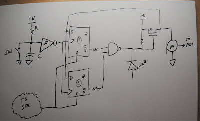
As far as I understood from the schematic [0], the power line of the mic is directly connected to the LED. Looks like when you press the mute button, you both light the led up and pull-up the transistor gate (It looks like PNP so, it turns off when you apply power to the gate). This effectively cuts off power from the mic itself. So, the LED is not controlled by firmware but, by the behavior of the circuit. AFAIK, OTA updates cannot re-wire PCBs or do we have nanobots now? [0]: https://1.bp.blogspot.com/-vVhoXpEtTXo/X_0iLmz9gcI/AAAAAAAAB... |
|
|